Kategorien
Coding Tinkering

Writing my own x86_64 Operating System

tl;dr Repo: https://github.com/jbreu/jos

During mid of last year I dug myself into the OS development rabbit hole on Youtube and in my fall vacation I had some slack allowing me to hands-on hack together my own Operating System called JOS (Jakob’s OS). This was the starting point of a pretty exciting journey. Till today, there is no particular purpose or goal other than learning more about low level basics. Nonetheless, I enjoyed this exercise so much that I can even grant it some therapeutic effect during very stressful business life 🙂 Of course, as a family father and engineering manager, there is not much time and I often found myself pondering in my mind while doing chores how to solve the next stack corruption puzzle, instead of actually coding/debugging. In this article, I will tell you a bit about my key learnings/technologies this exposed me to.

The starting point was a brief video series by David Callanan on how to write a bootloader for an OS till printing a Hello World to a console. I started to fork his repo and worked my way from there. First thing was to rewrite the whole OS code (besides the bootloader) in Rust, as this was another thing I wanted to learn. It took me a while to get used to Rust, but eventually came to a working Hello World. The next steps were minor adaptions to the console printing ecosystem. The first real big step digging into the intrinsics of x86_64 CPU instruction set was the implementation of interrupts. This took a great amount of debugging, trial and erroring and reading of many specifications and internet resources. From the latter, I want to highlight the AMD64 Architecture Programmer’s Manual, Volume 2, and Philipp Oppermann’s Writing an OS in Rust. The latter is really good for the first steps with one caveat: It is based in big parts on the author’s library, which abstracts all x86_64 basics away and is in many parts more a tutorial to use the library. I didnt want to use this library because my impression was that it masked too much of the interesting stuff how things actually work on the low level. Hence, I implement everything on my own terms. After adopting keyboard and time interrupts I used the latter to display the clock time on the console in the top right corner.

A huge help was that I could use the qemu emulator and the gdb debugger in combination (via VS Code’s extension native-debug). It was the first time using qemu and gdb as a developer and after getting beyond the initial learning curve I genuinely enjoyed debugging with it. As additional tools I also used Ghidra (disassembler) and ElfViewer (inspect executables).

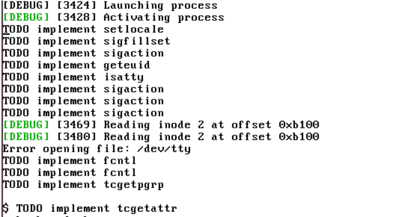
A really huge next step for me was to introduce userspace programs and later on multiprocessing (running multiple userspace programs „in parallel“ with a simple round robin scheduler). After studying basic patterns for this, I chose the hard path to implement it mostly by myself. This is the part which I am most proud of so far, because this required me to derive many inner works from the specs directly and it has cost me a long time to get right. For weeks and months I fought with sporadic stack corruptions and CPU exceptions. As userspace program I implemented a simple Hello World program, which interacted with the kernel via syscalls. Due to lack of a file system, which to date I was for some reasons not eager to implement, this userspace progam is stored inside the os executable and loaded from there – a hack which is actually really cool. Then I added a vga mode which enabled the userspace programs to print colored pixels to the screen (one line for each of the 4 userspace programs):

OK so here we were, but what you gonna do with an operating system which has keyboard input, can run user programs, has vga output? Yes, you are correct – we run Doom on it 🙂

You probably heard of people getting to run Doom on all sorts of awkward devices, engineers made it to run on potato batteries and toothbrushes:

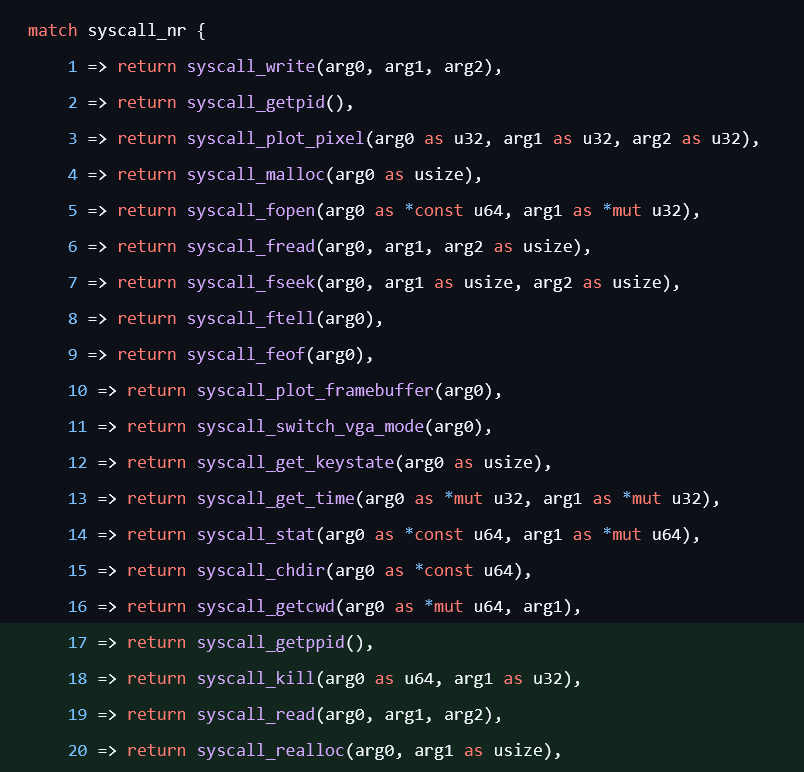
So if they can run it on such devices, there must be a way to run it on JOS, right? And yes, its possible. It required me to write a small C wrapper around PureDOOM, which in turn also made me translate my Rust-based libc to C. After adding some additional syscalls, fighting with the 6 bit color maps, malloc implementation I finally made it. So here we stand today, JOS runs DOOM.

Kategorien
Coding Tinkering

Simple CI/CD for embedded devices

After some years of private tinkering with CI/CD workflows for web development, and a good load of professional exposure to embedded projects working hard to get CI/CD in a scaling, fast and reliable setup, I wanted to combine both. Earlier, I did some trial-and-error-project leveraging the great NodeMCU boards, but it was without any automated testing and no ci pipelines used. So it was time to make a step further in my private endeavors and setup a CI/CD pipeline with automated flashing and testing of new embedded code. An important requirements was that the automated testing should test the complete embedded device consisting of its hardware and software in completeness (black box test). Hence, only the „official“ outside interfaces like serial interface and physical output (LED!) should be used for automated tests. Of course, the used hardware, software and complexity in no way match what our projects‘ engineering teams handle every day, and I don’t intend to compete with the engineers. Its an exercise for myself to learn.

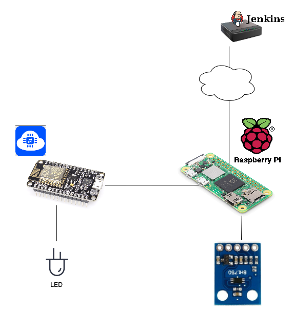
Without further ado, lets have a look at the setup:

We see the following: My vserver-hosted Jenkins is the same as usual. However, as local node connected to the target device (NodeMCU), I am using a Raspberry Pi Zero 2 W. I connected it as a node (formerly called slave) to my Jenkins master. The NodeMCU target is connected via a USB cable to that Raspberry Pi. The Raspi is able to build the code, flash it to the NodeMCU and run some tests written with Python. The NodeMCU target has an LED (with resistor) connected, which is controlled by the embedded software. To close the circle, the Raspi also has a BH1750 light detector board connected. The idea is: Whenever a software change is built and flashed, the Raspi can automaticall test if the LED is correctly lit, and if not, fail the test, hence the overall pipeline.

Eventually, with some vacation-breaks I made this work. Yay! There were, however, some impediments to overcome. You can find them here in case you would ever have a similar endeavor 🙂

  • To build the software on the Raspi, I had to install on it the according framework. After great experience with it on the desktop VSCode extension, I learned in the docs that PlatformIO also has a headless cli client. How to get it onto the Raspi? First I thought using a docker container would be a good choice, to have a reproducible environment. However, it was really hard to find any working, up-to-date docker for that. Hence, I finally decided to got with PlatformIO’s super-handy installer script.
  • Getting the LED to work with some simple code was not as straightfoward as I hoped after studying the docs initially. I could not make the LED light up at 50% no matter what I did to the values or wire connections. It was always at full power (which would be generally fine but not with the „product“ I had in mind, more on that in a later blog post I guess). I even used my simple osciloscope. Finally, it turned out that all the tutorials which explained this dead-simple setup had one snag: the provided value range had beed changed as a breaking change quite recently. After adapting to the new range it worked!
  • The BH1750 light sensor is connected with an I2C connection to the Raspi, which was my first own engineering exposure to I2C ever. In my first attempt I could connect it to the NodeMCU successfully, but after some travel and trying the same via the Raspi failed miserably. Again a lot of trial-and-error, until some random guys with the same issues on the interner hinted towards the pin connection on the BH1750. Indeed, it was extremely sensitive and the pins were always a bit off. I finally soldered it together and then it worked like a charm.
  • Using a Raspberry Pi Zero 2 to build the embedded software doesn’t sound very proper, and indeed a clean build takes a while and mostly blocks the complete machine for other things. The good news is that PlatformIO offers a simple out-of-the-box build cache solution, which requires not more than configuring a build cache directory, which is subsequently used. Of course, caches should always used with care and for reproducible build they should probably be turned off. Again, in my very simple setup it does its job.

So, as usual I spent most time debugging unexpected snags than on the actual concept or missing pieces. Still learned a lot.

I still have some open to-dos and followups:

  • Of course, my current „product“ is dead simple. Having the basics in place I want to extend the functionality gradually. With this minimal CI setup I can add/modify functionality without introducing regressions on the existing functionality.
  • Improve the pipeline duration. The average pipeline takes about 1 min, of which the flashing consumes the majority (30-40 secs) of time. Also there is a significant waiting time in the beginning which Jenkins does not include in the pipeline duration. I need to investigate what that is about.
  • At the moment the software is updated via USB cable. The NodeMCU framework also offers software update over the air (OTA). Leveraging that would some more flexibility in placing the device, and of course enabling Continuous Deployment on „production targets“. A first step I am considering is adding OTA as a second flash procedure, followed by another test run.
  • Exploring more options of NodeMCU’s and PlatformIO’s frameworks/tools. While setting up the above, I saw a lot of interesting things worth to investigate further.

Here is the (shortened) Jenkins log for reference:

Push event to branch master
Looking up repository jakob/NodeCI
Querying the current revision of branch master...
[...]
[Pipeline] Start of Pipeline
[Pipeline] node
Running on rpizero in /home/jakob/jenkinsnode/workspace/Jakob_NodeCI_master
[Pipeline] {
[Pipeline] stage
[Pipeline] { (Declarative: Checkout SCM)
[Pipeline] checkout
The recommended git tool is: NONE
using credential [...]
Fetching changes from the remote Git repository
Fetching without tags
[...]
Commit message: "added acceptace test for physical led"
 > /usr/bin/git config core.sparsecheckout # timeout=10
 > /usr/bin/git checkout -f
[...]
[Gitea] Notifying branch build status: PENDING Build started...
[Gitea] Notified
[Pipeline] }
[Pipeline] // stage
[Pipeline] withEnv
[Pipeline] {
[Pipeline] stage
[Pipeline] { (build)
[Pipeline] sh
+ /home/jakob/.platformio/penv/bin/pio run
Processing nodemcuv2 (platform: espressif8266; board: nodemcuv2; framework: arduino)
--------------------------------------------------------------------------------
Verbose mode can be enabled via `-v, --verbose` option
CONFIGURATION: https://docs.platformio.org/page/boards/espressif8266/nodemcuv2.html
PLATFORM: Espressif 8266 (3.2.0) > NodeMCU 1.0 (ESP-12E Module)
HARDWARE: ESP8266 80MHz, 80KB RAM, 4MB Flash
PACKAGES: 
 - framework-arduinoespressif8266 3.30002.0 (3.0.2) 
 - tool-esptool 1.413.0 (4.13) 
 - tool-esptoolpy 1.30000.201119 (3.0.0) 
 - toolchain-xtensa 2.100300.210717 (10.3.0)
LDF: Library Dependency Finder -> https://bit.ly/configure-pio-ldf
LDF Modes: Finder ~ chain, Compatibility ~ soft
Found 36 compatible libraries
Scanning dependencies...
No dependencies
Building in release mode
Retrieving maximum program size .pio/build/nodemcuv2/firmware.elf
Checking size .pio/build/nodemcuv2/firmware.elf
Advanced Memory Usage is available via "PlatformIO Home > Project Inspect"
RAM:   [===       ]  34.3% (used 28088 bytes from 81920 bytes)
Flash: [===       ]  25.7% (used 268009 bytes from 1044464 bytes)
========================= [SUCCESS] Took 7.07 seconds =========================
[Pipeline] }
[Pipeline] // stage
[Pipeline] stage
[Pipeline] { (flash)
[Pipeline] sh
+ /home/jakob/.platformio/penv/bin/pio run --target upload
Processing nodemcuv2 (platform: espressif8266; board: nodemcuv2; framework: arduino)
--------------------------------------------------------------------------------
Verbose mode can be enabled via `-v, --verbose` option
CONFIGURATION: https://docs.platformio.org/page/boards/espressif8266/nodemcuv2.html
PLATFORM: Espressif 8266 (3.2.0) > NodeMCU 1.0 (ESP-12E Module)
HARDWARE: ESP8266 80MHz, 80KB RAM, 4MB Flash
PACKAGES: 
 - framework-arduinoespressif8266 3.30002.0 (3.0.2) 
 - tool-esptool 1.413.0 (4.13) 
 - tool-esptoolpy 1.30000.201119 (3.0.0) 
 - tool-mklittlefs 1.203.210628 (2.3) 
 - tool-mkspiffs 1.200.0 (2.0) 
 - toolchain-xtensa 2.100300.210717 (10.3.0)
LDF: Library Dependency Finder -> https://bit.ly/configure-pio-ldf
LDF Modes: Finder ~ chain, Compatibility ~ soft
Found 36 compatible libraries
Scanning dependencies...
No dependencies
Building in release mode
Retrieving maximum program size .pio/build/nodemcuv2/firmware.elf
Checking size .pio/build/nodemcuv2/firmware.elf
Advanced Memory Usage is available via "PlatformIO Home > Project Inspect"
RAM:   [===       ]  34.3% (used 28088 bytes from 81920 bytes)
Flash: [===       ]  25.7% (used 268009 bytes from 1044464 bytes)
Configuring upload protocol...
AVAILABLE: espota, esptool
CURRENT: upload_protocol = esptool
Looking for upload port...

Warning! Please install `99-platformio-udev.rules`. 
More details: https://docs.platformio.org/page/faq.html#platformio-udev-rules

Auto-detected: /dev/ttyUSB0
Uploading .pio/build/nodemcuv2/firmware.bin
esptool.py v3.0
Serial port /dev/ttyUSB0
Connecting....
Chip is ESP8266EX
Features: WiFi
Crystal is 26MHz
MAC: e0:98:06:85:d6:23
Uploading stub...
Running stub...
Stub running...
Configuring flash size...
Compressed 272160 bytes to 199933...
Writing at 0x00000000... (7 %)
Writing at 0x00004000... (15 %)
Writing at 0x00008000... (23 %)
Writing at 0x0000c000... (30 %)
Writing at 0x00010000... (38 %)
Writing at 0x00014000... (46 %)
Writing at 0x00018000... (53 %)
Writing at 0x0001c000... (61 %)
Writing at 0x00020000... (69 %)
Writing at 0x00024000... (76 %)
Writing at 0x00028000... (84 %)
Writing at 0x0002c000... (92 %)
Writing at 0x00030000... (100 %)
Wrote 272160 bytes (199933 compressed) at 0x00000000 in 18.0 seconds (effective 121.2 kbit/s)...
Hash of data verified.

Leaving...
Hard resetting via RTS pin...
========================= [SUCCESS] Took 27.74 seconds =========================
[Pipeline] }
[Pipeline] // stage
[Pipeline] stage
[Pipeline] { (test)
[Pipeline] sh
+ python test/acceptance.py -v
testHelloWorld (__main__.AcceptanceTests) ... ok
testLEDIsTurnedOn (__main__.AcceptanceTests) ... ok

----------------------------------------------------------------------
Ran 2 tests in 0.743s

OK
[Pipeline] }
[Pipeline] // stage
[Pipeline] }
[Pipeline] // withEnv
[Pipeline] }
[Pipeline] // node
[Pipeline] End of Pipeline
[Gitea] Notifying branch build status: SUCCESS This commit looks good
[Gitea] Notified
Finished: SUCCESS

Kategorien
Tinkering

3D Printing Periphery

Some of my reader already know: A few months ago my wife and me bought a 3d printer, the Prusa MK3S+ (yes, she was pushing this). We decided for the self assembly version, which did not only save us some €, but while we assembled the device we learned a lot about its construction. By the way, the self-assembly handbook were the best printed instructions I ever saw, much recommended.

While my wife focuses on designing impressive organic 3d models with Blender, I envisioned my main usage for tinkering and maker products. It turns out, the printer itself is also a great target for tinkering 🙂 Today, I reached a major milestone, hence I thought about making this short writeup, as inspiration for others and reminder for future self.

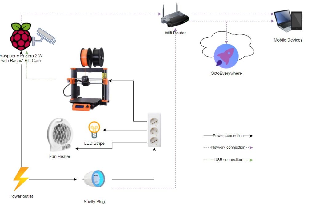
One wiring diagram says more than thousands words:

Some bullet points:

  • The Raspberry Pi Zero 2 W (just got available a few weeks back) is always connected to the power and wifi of course.
  • The Raspi runs current versions of OctoPi/OctoPrint with some fancy plugins, so the typical operation and monitoring can all happen from any device with a browser.
  • The Raspi is equipped with the RaspiZ HD Cam.
  • I had some issues with the Raspi file system getting corrupted when there was power loss, leading to unavailability from the network. Which was kind of a dilemma, because how could I turn off this headless device without being able to connect via SSH and shutdown? The solution is an extra hard button soldered to the Raspi’s GPIO pins. When this button gets clicked, the Raspi is running its proper shutdown sequence (which should not be required in many cases).
  • As the images/videos from the camera where too dark even with the room lights on, I added an LED stripe behind the camera so its illuminating the printer
  • The printer is in a room which can get quite cold in winter, and low temperature stops the printer from being available (some safety thresholds kick in), we use a fan heater to get the temperature to the required minimum in the room. (Yes I am aware that the printer should be stored at room temperature the whole year, but we dont have space for that. Something to fix later.)
  • The printer, heater and LEDs can all be turned on and off via a remote controllable Shelly Plug. The nice perk here is that there are plugins to make the power switching available in the OctoPrint UI (PSU Control and its Shelly sub-plugin)
  • OctoPrint is directly available from the LAN, and for internet accessibility I recently started to use OctoEverywhere.

I think its a nice setup so far, and still more ideas to improve. Its not recommended to use the 3d printer in absence, even with remote monitoring. I am thinking about adding some fire/smoke detection device to the setup.